Mechanical Cross-Section Analysis (X-Section)
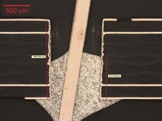
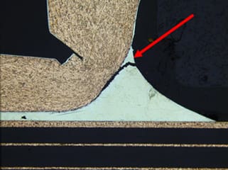
Mechanical cross-section analysis enables one to expose buried features on a sample in a controlled fashion. It is regularly used in IPC compliance testing, to assay critical dimensions, or to identify miscellaneous structural defects or abnormalities such as cracks, bridging, delamination, deformations, and more.
Covalent Metrology’s technical staff have over 30 years of experience in the preparation and measurement of sample cross-sections. In addition, our team is certified to conduct IPC-qualified cross-sectional procedures for PCB failure analysis and quality control.
Strengths
- High-resolution structural analysis for internal features of components, assemblies, and substrates
- Can be combined with EDS / EDX for elemental mapping
- Robust documentation and compliance standards available
Limitations
- Destructive analysis
- Multiple cross-sectional samples are required to evaluate all pins on most electronic components / PCBs
- Technique is highly manual and extensive expertise is required to properly prepare samples. Improperly prepared samples can produce misleading artifacts