Mechanical Cross-Section Analysis (X-Section)
Mechanical Cross-Section Analysis Main Image
Through-Pin solder joint showing hole-fill is <75%, which is a defect per IPC-A-610G, section 7.3.5.1.

Mechanical cross-section analysis enables one to expose buried features on a sample in a controlled fashion. It is regularly used in IPC compliance testing, to assay critical dimensions, or to identify miscellaneous structural defects or abnormalities such as cracks, bridging, delamination, deformations, and more.

Covalent Metrology’s technical staff have over 30 years of experience in the preparation and measurement of sample cross-sections. In addition, our team is certified to conduct IPC-qualified cross-sectional procedures for PCB failure analysis and quality control.

Strengths

  • High-resolution structural analysis for internal features of components, assemblies, and substrates
  • Can be combined with EDS / EDX for elemental mapping
  • Robust documentation and compliance standards available

Limitations

  • Destructive analysis
  • Multiple cross-sectional samples are required to evaluate all pins on most electronic components / PCBs
  • Technique is highly manual and extensive expertise is required to properly prepare samples. Improperly prepared samples can produce misleading artifacts

Learn More

Mechanical Cross-Section Analysis Services

Mechanical Cross-Section Analysis

Mechanical cross-section analysis enables one to expose buried features on a sample in a controlled fashion. It is regularly used in IPC compliance testing, to assay critical dimensions, or to identify miscellaneous structural defects or abnormalities such as cracks, bridging, delamination, deformations, and more.

Covalent Metrology’s technical staff have over 30 years of experience in the preparation and measurement of sample cross-sections. In addition, our team is certified to conduct IPC-qualified cross-sectional procedures for PCB failure analysis and quality control.

Sample Requirements

Example Outputs

BGA Device showing minimal warpage. Solder joins were confirmed acceptable per IPC-A-610G, section 8.3.12.

BGA solder joint showing wetting and solder joint shape are acceptable per IPC-A-610G, section 8.3.12. This mixed alloy solder joint shows full mixing of Pb from the solder paste into the Pb-free solder ball.

Through-Pin solder joint showing hole-fill is <75%, which is a defect per IPC-A-610G, section 7.3.5.1.

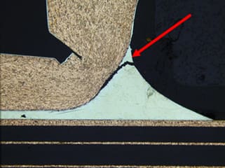
Heel fillet crack, which is a defect per IPC-A-610G, section 5.2.9.

Inner Layer Separation, which is non-conforming per IPC-A-600J, section 3.3.6.

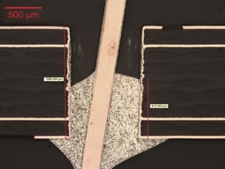
Plated Through-Hole (PTH) showing copper plating thickness in the center region is below the minimum requirement of 18um in IPC-6012B, Table 3-4.

How X-Section Works

Mechanical Cross-Section Analysis is regularly used to identify miscellaneous structural defects or abnormalities such as: cracks, bridging, delamination, deformations, and more.

In addition, in areas where FIB-SEM is not used to expose a cross-section, mechanical cross-sectioning can be a cost effective alternative to characterize large regions of a sample.

To prepare sample cross sections, components or regions of interest are manually extracted, usually by physical cutting with an abrasive or cleaving tool. Next, these extracted pieces are encapsulated in epoxy resin, which retains the true structure of the sample during subsequent processing.

Once encapsulated, the samples are polished to enhance clarity and surface uniformity, and to target the feature of interest at the surface of the resin puck. When polishing reaches the target location (e.g. the center of a solder joint), intermediate and final polishing steps are used to achieve a sub-micron finish roughness.

Details in the cross-section layer structures may be enhanced with a light chemical etch, finalizing the sample for subsequent imaging and analysis via Scanning Electron Microscopy (SEM) or Digital Optical Microscopy.